Using DS18B20 on RPi (python) w/bonus writing to InfluxDB

This is how I used 3 x DS18B20 digital temperature sensors wired to a RPi. I bought the versions sealed in a casing as plan to put them outdoors. All data handling done in python and being written to InfluxDB and finally displayed on Grafana.

If you want to first familiarise yourself with python and InfuxDB see an earlier post.

Connect the sensors to the RPi as shown below:

Image Source: Scott Campbell https://www.circuitbasics.com/raspberry-pi-ds18b20-temperature-sensor-tutorial/

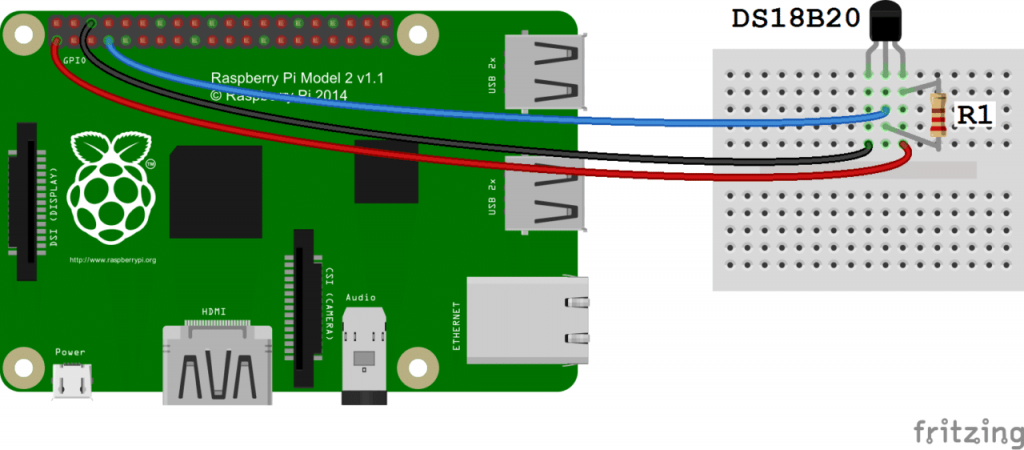
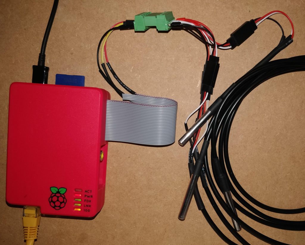
Sensors can be connected in parallel and no extra resistors required. I soldered onto the ribbon cable and used servo connectors to connect each sensor, this would make it easier to pass through glands later on. See my final setup below:

Anyway starting from a fresh install setup the RPi:

sudo apt-get update
sudo apt-get upgrade
sudo apt-get install python-influxdb

Enable the One-Wire interface for the DS18B20 by opening the below file:

sudo nano /boot/config.txt

And add the below to the bottom of the file:

dtoverlay=w1-gpio

Next exit (Ctrl + x) & reboot:

sudo reboot

Next lets see if device detected:

sudo modprobe w1-gpio
sudo modprobe w1-therm
cd /sys/bus/w1/devices
ls

In my case: (when I only connected 1 sensor, the others showed up when connect them)

28-3c01d60708e8 w1_bus_master1

is displayed. Now enter: (change the X’s to your own address or hit tab to auto-fill)

cd 28-XXXXXXXXXXXX
cat w1_slave

The raw temperature reading output by the sensor will be show as below:

4f 01 55 05 7f a5 81 66 3b : crc=3b YES
4f 01 55 05 7f a5 81 66 3b t=20937

Here the temperature reading is t=20937, which means a temperature of 20.937 degrees Celsius.

Great so we are reading a single sensor fine, lets create a python file to do all the above for us:

cd /home/pi
nano temp.py

Fill the file with the below: Remember to update the below:
– The IP of your InfluxDB instance along with database details.
– The address of your DS18B20 sensors

import os
import glob
import time

os.system('modprobe w1-gpio')
os.system('modprobe w1-therm')

from influxdb import InfluxDBClient
client = InfluxDBClient(host='192.168.1.XXX', port=8086)
#client.get_list_database()
client.switch_database('YOUR_DATABASE')

sensor_1 = '/sys/bus/w1/devices/28-3c01d60708e8/w1_slave'
sensor_2 = '/sys/bus/w1/devices/28-3c01d60711da/w1_slave'
sensor_3 = '/sys/bus/w1/devices/28-3c01d6072d92/w1_slave'

sensor_1_t = 0
sensor_2_t = 0
sensor_3_t = 0

def read_temp(sensor):
    f = open(sensor, 'r')
    lines = f.readlines()
    f.close()

    equals_pos = lines[1].find('t=')
    if equals_pos != -1:
        temp_string = lines[1][equals_pos+2:]
        temp_c = float(temp_string) / 1000.0
        return temp_c

sensor_1_t = read_temp(sensor_1)
sensor_2_t = read_temp(sensor_2)
sensor_3_t = read_temp(sensor_3)

print("Sensor 1 (Inside Shed): " + str(sensor_1_t))
print("Sensor 2 (Outside): " + str(sensor_2_t))
print("Sensor 3 (Soil): " + str(sensor_3_t))

json_body = [
    {
        "measurement": "YOUR_MEASUREMENT",
        "tags": {
            "Device": "YOUR_DEVICE",
            "ID": "YOUR_ID"
        },
        "fields": {
            "i_temp": sensor_1_t,
            "o_temp": sensor_2_t,
            "s_temp": sensor_3_t
        }
    }
]
client.write_points(json_body)

Exit the nano editor while saving using Ctrl + x and hitting Y to save. Make the file executable:

chmod +x temp.py

Run the python file:

python temp.py

Data will be written to your database along with the text outputted to the console. Okay now lets get it to run/log every 15mins by:

crontab -e
*/15 * * * * /usr/bin/python /home/pi/temp.py

Ctrl + x to exit

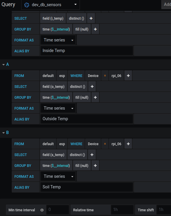
I then setup a Grafana display to show the sensors (all in the same location for now)
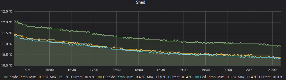
Settings used for above display.

That’s it!

Resources I used:
https://www.circuitbasics.com/raspberry-pi-ds18b20-temperature-sensor-tutorial/

IOT Geiger Counter (InfluxDB)

Of course every household needs a Geiger Counter and I bought this kit to do all the fancy 400/500V voltage work along with an SBM-20 Geiger-Muller Tube on eBay for the actual radiation detecting. Typically it seems people hook this up to a tablet etc. and run an app but my plan was to log to InfluxDB. It can also operate stand-alone which is why I added a handy display (Nokia 5110).

Finished IOT Geiger Counter

Notes:
This type of detector is designed to detect Beta & Gamma rays. (it cannot detect Alpha rays but this sensor can be added easily if wanted.

What it does:
– Listens & counts pulses for 60 seconds
– After 60 seconds writes this value to InfluxDB
– Updates display with current metrics. (last 60 second reading, average reading, max reading, estimated dosage & the current IP address)

Connecting it up:

LCD PinESP8266 Labelled PinESP8266 GPIO PinGeiger Detector Board
1 – RSTD0GPIO 16
2 – CED1GPIO 5
3 – DCD2GPIO 4
4 – DIND3GPIO 0
5 – CLKD4GPIO 2
6 – Vcc3.3V3.3V
7 – Backlight3.3V (on)3.3V
8 – GroundGroundGroundGround
D5GPIO 14Int (interrupt)
VU/ 5VVU / 5V5V

Code:
See latest code at my GitHub (or below):
– Requires Adafruit libraries. Link 1, Link 2
– Requires Running Average Library
– Requires InfluxDb library

#include <ESP8266WiFi.h>
#include <InfluxDb.h>
#include <SPI.h>
#include <Adafruit_GFX.h>
#include <Adafruit_PCD8544.h>
#include "RunningAverage.h"

#define INFLUXDB_HOST "192.168.1.XXX"
#define WIFI_SSID "XXXXXXXXXXXX"
#define WIFI_PASS "XXXXXXXXXXXX"
#define DATABASE "XXXXXXXXXXXX"
#define MEASUREMENT "XXXXXXXXXXXX"
#define DEVICE "XXXXXXXXXXXX"
#define ID "Geiger_Counter"
#define LOG_PERIOD 60000

Influxdb influx(INFLUXDB_HOST);
Adafruit_PCD8544 display = Adafruit_PCD8544(2, 0, 4, 5, 16); //LCD 1.5 Inch (Nokia 5110)84×48 (x,y) pixels
RunningAverage raMinute(60);

//################
int debug = 1; //#
//################

int loopCount = 0;
int cpm = 0;
int cpm_max = 0;
int cpm_1hr_avg = 0;
int cpm_ravg = 0;
int counts = 0;
int cal_factor = 1;
int wifiStatus;

unsigned long currentMillis;
unsigned long previousMillis; //variable for time measurement

void setup(){                                               
  Serial.begin(9600);      // start serial monitor
  delay(1000);
  Serial.println("");
  Serial.println("");
  Serial.println("Setup Routine of ESP8266 Geiger Counter");

  display.begin();
  display.setContrast(55);
  display.display();        // show adafruid splashscreen
  delay(2000);
  display.clearDisplay();   // clears the screen and buffer

  pinMode(LED_BUILTIN, OUTPUT); //D4
  digitalWrite(LED_BUILTIN, HIGH); //Turns it off

  pinMode(14, INPUT_PULLUP);                  // set pin INT0 input for capturing GM Tube events / GPIO5 = D1
  attachInterrupt(14, tube_pulse, FALLING); //defines interrupts

  raMinute.clear();

  influx.setDb(DATABASE);

  display.setTextSize(1);
  display.setTextColor(BLACK);
  display.setCursor(0,0); display.setTextSize(1);display.print("Up Hrs: ");display.setCursor(48,0);display.print("0");
  display.setCursor(0,9); display.setTextSize(1);display.print("CPMi 1m:");
  display.setCursor(0,17);display.setTextSize(1);display.print("CPM avg:");
  display.setCursor(0,25);display.setTextSize(1);display.print("CPM Max:");
  display.setCursor(0,33);display.setTextSize(1);display.print("uSv/hr: ");
  display.setCursor(0,41);display.setTextSize(1);display.print("Not Connected");
  display.display();

    wifiStatus = WiFi.status();
    if (wifiStatus != WL_CONNECTED) {   
      new_connection();
    }
    else {
        display.fillRect(0,41,84,48, WHITE);
        display.setCursor(0,41);
        display.print(WiFi.localIP());
        display.display();
    }
    

  if (debug == 1) {Serial.println("Setup Complete.");}
}

void loop(){                                              
  currentMillis = millis();
  if(currentMillis - previousMillis > LOG_PERIOD){
    cpm = counts * cal_factor;                        

    raMinute.addValue(cpm);
    cpm_ravg = raMinute.getAverage();

    if (cpm > cpm_max){
      cpm_max = cpm;
    }
    
    Serial.print("CPM: ");                         
    Serial.println(cpm);                          

    display.fillRect(48,0,40,40, WHITE);
    display.display();
    display.setCursor(48,0);display.print(loopCount*.0166);
    display.setCursor(48,9);display.print(cpm);
    display.setCursor(48,17);display.print(cpm_ravg);
    display.setCursor(48,25);display.print(cpm_max);
    display.setCursor(48,33);display.print(cpm_ravg*0.0057);
    display.display();

    Serial.println("Attempting to write to DB");   
    counts = 0;

    InfluxData row(MEASUREMENT);
    row.addTag("Device", DEVICE);
    row.addTag("ID", ID);
    row.addValue("CPM", cpm);  
    row.addValue("LoopCount", loopCount);
    row.addValue("RandomValue", random(0, 100));
  
    wifiStatus = WiFi.status();
    while ( wifiStatus != WL_CONNECTED )
        {
          new_connection();
        }
  
    influx.write(row);
    if (debug == 1) {Serial.println("Wrote Data.");}
  
    //WiFi.mode(WIFI_OFF); // Probably turn off Wifi if want to save battery
    //WiFi.forceSleepBegin();
    //delay( 1 );
  
    status_blink();
    previousMillis = currentMillis;
    loopCount++;
  }
}

ICACHE_RAM_ATTR        //Needed to fix ISR not in IRAM boot error
void tube_pulse(){     //procedure for capturing events from interrupt
  counts++;
}

void new_connection() {
  
    wifiStatus = WiFi.status();
    
    if (wifiStatus != WL_CONNECTED) {   
       
        WiFi.mode(WIFI_STA);
        WiFi.begin(WIFI_SSID, WIFI_PASS);
        int loops = 0;
        int retries = 0;
        display.fillRect(0,41,84,48, WHITE);
        display.setCursor(0,41);
        display.print("Not Connected");
        display.display();
       
        while (wifiStatus != WL_CONNECTED)
        {
          retries++;
          if( retries == 300 )
          {
              if (debug == 1) {Serial.println( "No connection after 300 steps, powercycling the WiFi radio. I have seen this work when the connection is unstable" );}
              WiFi.disconnect();
              delay( 10 );
              WiFi.forceSleepBegin();
              delay( 10 );
              WiFi.forceSleepWake();
              delay( 10 );
              WiFi.begin( WIFI_SSID, WIFI_PASS );
          }
          if ( retries == 600 )
          {
              if (debug == 1) {Serial.println( "No connection after 600 steps. WiFi connection failed, disabled WiFi and waiting for a minute" );}
              WiFi.disconnect( true );
              delay( 1 );
              WiFi.mode( WIFI_OFF );
              WiFi.forceSleepBegin();
              delay( 10 );
              retries = 0;
              
              if( loops == 3 )
              {
                  if (debug == 1) {Serial.println( "That was 3 loops, still no connection so let's go to deep sleep for 2 minutes" );}
                  Serial.flush();
                  ESP.deepSleep( 120000000, WAKE_RF_DISABLED );
              }     
          }
          delay(50);
          wifiStatus = WiFi.status();
        }
        
        wifiStatus = WiFi.status();
        Serial.print("WiFi connected, IP address: ");Serial.println(WiFi.localIP());
        display.fillRect(0,41,84,48, WHITE);
        display.setCursor(0,41);
        display.print(WiFi.localIP());
        display.display();
    }
}

void status_blink() {
  digitalWrite(LED_BUILTIN, LOW);   // Turn the LED on (Note that LOW is the voltage level   
  delay(100);
  digitalWrite(LED_BUILTIN, HIGH);   // Turn the LED on (Note that LOW is the voltage level
  delay(100);
  digitalWrite(LED_BUILTIN, LOW);   // Turn the LED on (Note that LOW is the voltage level   
  delay(100);
  digitalWrite(LED_BUILTIN, HIGH);   // Turn the LED on (Note that LOW is the voltage level
}

ToDo:
– Comment code
– Add in check at start of code to see if tube functioning.
– I would like to update the running average to 60min average but not enough time to currently do these 10 lines of code.
– Add in control (on/off ) for the LCD backlight, buzzer & Wifi for battery consumption.
– Perhaps would be nice to log to SD card also, not sure if I still have enough I/O for that.
– The ‘case’ is a very rough and not worthy of sharing, a nicer more bespoke would be ideal.
– Add radiation symbol on splash screen.

Resources I used:
https://mightyohm.com/blog/2014/11/a-spotters-guide-to-the-sbm-20-geiger-counter-tube/

That’s it!

ESP8266 logging to InfluxDB (Ver 1.x & 2.x)

The ESP8266 is a $5 IOT device with huge capabilities. In this post we will log data to a remote Influx database running on a RaspberryPi.

I am programming the ESP8266 in the Arduino IDE, the ESP8266 library is required, you can find it here. I have a test code file (of copy from below) that you can upload after entering your InfluxDB I.P. Address, SSID & Password and it will start logging data immediately.

Code for InfluxDB Version 1.x (Version 1.6 specifically for me.)

#include <ESP8266WiFi.h>
#include <ESP8266WiFiMulti.h>
#include <InfluxDb.h>

#define INFLUXDB_HOST "192.168.1.1"   //Enter IP of device running Influx Database
#define WIFI_SSID "SSID"              //Enter SSID of your WIFI Access Point
#define WIFI_PASS "PASSWORD"          //Enter Password of your WIFI Access Point

ESP8266WiFiMulti WiFiMulti;
Influxdb influx(INFLUXDB_HOST);

void setup() {
  Serial.begin(9600);
  WiFiMulti.addAP(WIFI_SSID, WIFI_PASS);
  Serial.print("Connecting to WIFI");
  while (WiFiMulti.run() != WL_CONNECTED) {
    Serial.print(".");
    delay(100);
  }
  Serial.println("WiFi connected");
  Serial.println("IP address: ");
  Serial.println(WiFi.localIP());

  influx.setDb("esp8266_test");

  Serial.println("Setup Complete.");
}

int loopCount = 0;

void loop() {
  loopCount++;

  InfluxData row("data");
  row.addTag("Device", "ESP8266");
  row.addTag("Sensor", "Temp");
  row.addTag("Unit", "Celsius");
  row.addValue("LoopCount", loopCount);
  row.addValue("RandomValue", random(10, 40));

  influx.write(row);
  delay(5000);
}

Code for InfluxDB Version 2.x (Version 2.1 specifically for me). Download Arduino library from here.

#include <ESP8266WiFi.h>
#include <ESP8266WiFiMulti.h>
#include <InfluxDb.h>

#define INFLUXDB_URL "http://192.168.1.XXX:8086" // e.g. http://192.168.1.48:8086 (In InfluxDB 2 UI -> Load Data -> Client Libraries), 
#define INFLUXDB_TOKEN "YOUR_TOKEN" // InfluxDB 2 server or cloud API authentication token (Use: InfluxDB UI -> Load Data -> Tokens -> <select token>)
#define INFLUXDB_ORG "influx" // InfluxDB 2 organization id (Use: InfluxDB UI -> Settings -> Profile -> <name under tile> )
#define INFLUXDB_BUCKET "YOUR_BUCKET" // InfluxDB 2 bucket name (Use: InfluxDB UI -> Load Data -> Buckets)
#define WIFI_SSID "YOUR_SSID"
#define WIFI_PASS "YOUR_PASS"
#define MEASUREMENT "esp"
#define DEVICE "esp_04"
#define ID "Development ESP"

ESP8266WiFiMulti WiFiMulti;
InfluxDBClient client(INFLUXDB_URL, INFLUXDB_ORG, INFLUXDB_BUCKET, INFLUXDB_TOKEN);
Point row(MEASUREMENT); // Setup InfluxDB data point

void setup() {
  Serial.begin(9600);
  WiFiMulti.addAP(WIFI_SSID, WIFI_PASS);
  Serial.print("Connecting to WIFI");
  while (WiFiMulti.run() != WL_CONNECTED) {
    Serial.print(".");
    delay(100);
  }
  Serial.println("WiFi connected");
  Serial.println("IP address: ");
  Serial.println(WiFi.localIP());

  if (client.validateConnection()) {          // Checks if can communicate with InfluxDB server
      Serial.print("Connected to InfluxDB: ");
      Serial.println(client.getServerUrl());
  }
  else {
      Serial.print("InfluxDB connection failed: ");
      Serial.println(client.getLastErrorMessage());
  }

  Serial.println("Setup Complete.");
}

int loopCount = 0;

void loop() {
  loopCount++;

  row.clearFields();  // Clear Influx Fields
  row.clearTags();    // Clear Influx Tags
  row.addTag("Device", DEVICE);
  row.addTag("ID", ID);
  row.addField("LoopCount", loopCount);
  row.addField("RandomValue", random(0, 100)); //Helpful for debugging if needed.
  row.addField("25_Value", 20);
  row.addField("50_Value", 50); 
  row.addField("100_Value", 100);     

  Serial.print("Writing: "); // Print what are we exactly writing
  Serial.println(client.pointToLineProtocol(row));

      if (!client.writePoint(row)) {
        Serial.print("InfluxDB write failed: ");
        Serial.println(client.getLastErrorMessage());
      }
      else {
      Serial.println("Wrote data successfully");
      Serial.println("");
      }
  delay(5000);
}

The Arduino Serial Terminal will display something like the below so you can if it is working. (My previous tutorial shows setting up InfluxDB, ensure you have the database “esp8266_test” created as we are going to write to that.)

 --> writing to esp8266_test:
data,Device=ESP8266,Sensor=Temp,Unit=Celsius LoopCount=256.00,RandomValue=37.00
 <-- Response: 204 ""
 --> writing to esp8266_test:
data,Device=ESP8266,Sensor=Temp,Unit=Celsius LoopCount=257.00,RandomValue=20.00
 <-- Response: 204

On the Influx Database we can look at the data by:

influx
USE esp8266_test
select * from data limit 50

Below you can see the export from my database (I have shortened the time field for neatness). You can see I reset the ESP8266 a couple of times due to the LoopCount value.

time        Device  LoopCount RandomValue Sensor Unit    
----        ------  --------- ----------- ------ ----   
52808175073 ESP8266 1         38          Temp   Celsius                              
63108846141 ESP8266 2         35          Temp   Celsius                              
69802517277 ESP8266 1         13          Temp   Celsius                              
79892112240 ESP8266 2         12          Temp   Celsius                              
89961602267 ESP8266 3         14          Temp   Celsius                              
99998928411 ESP8266 4         22          Temp   Celsius                              
10053683452 ESP8266 5         10          Temp   Celsius                              
20120378415 ESP8266 6         28          Temp   Celsius                              
30175745403 ESP8266 7         14          Temp   Celsius                              
40732248123 ESP8266 8         38          Temp   Celsius                              
51232948067 ESP8266 9         15          Temp   Celsius                              
61322347831 ESP8266 10        13          Temp   Celsius                              
71424432515 ESP8266 11        19          Temp   Celsius                              
84740185749 ESP8266 1         18          Temp   Celsius                              
94790343615 ESP8266 2         21          Temp   Celsius                              
04839215465 ESP8266 3         13          Temp   Celsius                              
31864448941 ESP8266 1         32          Temp   Celsius                              
41956355523 ESP8266 2         36          Temp   Celsius                              
52018136222 ESP8266 3         30          Temp   Celsius                              
62083037888 ESP8266 4         22          Temp   Celsius       

That’s it!

Resources I used: